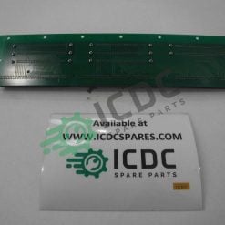
EATON – DILEM-10-G – Electronic Modules – ICDC-040659 – New
Main Category: Electronics | Sub-Category: Modules | Status: New Original Components
EATON Part Number: DILEM10G | ICDC Internal Part Number: ICDC-040659
DILEM-10-G Description:
DILEM-10-G (24VDC) – Power contactor, 3p + 1NO, 4kW / 400V / AC3
010213
SUPPLY PROGRAM
Assortment
Power contactors
Application
Miniature contactor for motors and ohmic loads
Below range
DILEM power contactors
Use category
AC-1: Non-inductive or weakly inductive load, resistance furnaces
AC-3 / AC-3e: squirrel-cage motors: starting, stopping during operation
AC-4: Squirrel-cage motors: starting, electric counter-current brakes, reversing, movements impulse
Note
Can also be used for IE3 efficiency class motors.
Also tested in accordance with AC-3e.
Types of connection
Screw terminals
Description
With auxiliary contacts
Poly
3-pole
Rated operational current
AC-3
380 V 400 V [I e ] 9 A
AC-1
conventional free air thermal current, 3 poles, 50 – 60 Hz
per day
at 40 ° C [I th =I and ] 22 A
Max. Rated power of use for three-phase motors 50 – 60 Hz
AC-3
220 V 230 V [P] 2.2 kW
AC-3
380 V 400 V [P] 4 kW
AC-3
660 V 690 V [P] 4 kW
AC-4
220V 230V [P] 1.5 kW
AC-4
380 V 400 V [P] 3 kW
AC-4
660 V 690 V [P] 3 kW
Contact equipment
NA = norm. open
1 NO contact
Note
Combination diode-resistance integrated in the coil
use with
… DILEM
… DILE
Control voltage
24 V DC
Type of current AC / DC
Direct current control
TECHNICAL DATA
Generality
Compliance with standards
IEC / EN 60947, VDE 0660, CSA, UL,
Mechanical life [Operations] 20 x 10 6
Maximum operating frequency
mechanics
9000 Man / h
Maximum operating frequency
electrical (contactors without thermal relay) [Operations / h] Page 05/070
Suitability for climates
Humid heat, constant, according to IEC 60068-2-78
Humid heat, cyclic according to IEC 60068-2-30
Room temperature
per day
-25 – +50 ° C
Room temperature
in custody
– 25 – 40 ° C
Room temperature
Storage
Ambient storage temperature min.
-40 ° C
Room temperature
Storage
Ambient temperature storage max.
+80 ° C
Mounting position
optional, except vertical with A1 / A2 terminals at the bottom
hock resistance (IEC / EN 60068-2-27)
Sinusoidal shock 10 ms
Basic unit without auxiliary contact module
Main contacts NO contact
10 g
Shock resistance (IEC / EN 60068-2-27)
Sinusoidal shock 10 ms
Basic unit without auxiliary contact module
Auxiliary contacts NC contact / NO contact
NO contact
8 g
Shock resistance (IEC / EN 60068-2-27)
Sinusoidal shock 10 ms
Basic device with auxiliary contact module
Main contact NO contact
NO contact
10 g
Shock resistance (IEC / EN 60068-2-27)
Sinusoidal shock 10 ms
Basic device with auxiliary contact module
Auxiliary contacts NO contact / NC contact
20/20 g
Degree of protection
IP20
Protection against accidental contact in case of frontal actuation (EN 50274)
Protection against finger and back of hand contact
Altitude
max. 2000 mm
Weight
0.206 kg
Auxiliary and main circuit connection sections
Screw terminals
Stiff
1 x (0.75 – 2.5)
2 x (0.75 – 2.5) mm 2
Auxiliary and main circuit connection sections
Screw terminals
Flexible with ferrule
1 x (0.75 – 1.5)
2 x (0.75 – 1.5) mm 2
Auxiliary and main circuit connection sections
Screw terminals
Single wire or stranded
18 – 14 AWG
Auxiliary and main circuit connection sections
Screw terminals
Stripping length
8 mm
Auxiliary and main circuit connection sections
Screw terminals
Connecting screw
M3.5
Auxiliary and main circuit connection sections
Screw terminals
Pozidriv screwdriver
2 Size
Auxiliary and main circuit connection sections
Screw terminals
Flat-blade screwdriver
0.8 x 5.5
1 x 6 mm
Auxiliary and main circuit connection sections
Screw terminals
Max. Clamping force
1.2 Nm
Main circuit
Rated impulse withstand voltage [U imp ] 6000 V AC
Overvoltage category / pollution degree
III / 3
Rated insulation voltage [U i ] 690 V AC
Rated operational voltage [U e ] 690 V AC
Safe isolation according to EN 61140
between coil and contacts
300 V AC
Safe isolation according to EN 61140
between contacts
300 V AC
Making capacity (cos ϕ according to IEC / EN 60947)
110 A
Opening power
220V 230V
90 A
Opening power
380 V 400 V
90 A
Opening power
500 V
64 A
Opening power
660 V 690 V
42 A
Short circuit protection fuse max
Tipe2, 500 V [gG / gL] 10 A
Short circuit protection fuse max
Tipe1, 500 V [gG / gL] 20 A
Alternating voltage
AC-1
Rated operational current
conventional free air thermal current, 3 poles, 50 – 60 Hz
per day
at 40 ° C [I th =I and ] 22 A
AC-1
Rated operational current
conventional free air thermal current, 3 poles, 50 – 60 Hz
per day
at 50 ° C [I th =I and ] 20 A
AC-1
Rated operational current
conventional free air thermal current, 3 poles, 50 – 60 Hz
per day
at 55 ° C [I th =I and ] 19 A
AC-1
Rated operational current
conventional free air thermal current, 3 poles, 50 – 60 Hz
in custody [I th ] 16 A
AC-1
Rated operational current
conventional free air thermal current, 3 poles, 50 – 60 Hz
Note
For the maximum permissible ambient temperature.
AC-1
Rated operational current
Conventional thermal current 1 pole
Note
For the maximum permissible ambient temperature.
AC-1
Rated operational current
Conventional thermal current 1 pole
per day [I th ] 50 A
AC-1
Rated operational current
Conventional thermal current 1 pole
in custody [I th ] 40 A
AC-3
Rated operational current
open, 3 poles, 50 – 60 Hz
Note
At maximum allowable ambient temperature (open)
Also tested in accordance with AC-3e.
AC-3
Rated operational current
open, 3 poles, 50 – 60 Hz
220V 230V [I e ] 9 A
AC-3
Rated operational current
open, 3 poles, 50 – 60 Hz
240 V [I e ] 9 A
AC-3
Rated operational current
open, 3 poles, 50 – 60 Hz
380 V 400 V [I e ] 9 A
AC-3
Rated operational current
open, 3 poles, 50 – 60 Hz
415 V [I e ] 9 A
AC-3
Rated operational current
open, 3 poles, 50 – 60 Hz
440 V [I e ] 9 A
AC-3
Rated operational current
open, 3 poles, 50 – 60 Hz
500 V [I e ] 6.4 A
AC-3
Rated operational current
open, 3 poles, 50 – 60 Hz
660 V 690 V [I e ] 4.8 A
AC-3
Rated absorbed power [P] 220 V 230 V [P] 2.2 kW
AC-3
Rated absorbed power [P] 240 V [P] 2.5 kW
AC-3
Rated absorbed power [P] 380 V 400 V [P] 4 kW
AC-3
Rated absorbed power [P] 415 V [P] 4.3 kW
AC-3
Rated absorbed power [P] 440 V [P] 4.6 kW
AC-3
Rated absorbed power [P] 500 V [P] 4 kW
AC-3
Rated absorbed power [P] 660 V 690 V [P] 4 kW
AC-4
Rated operational current
open, 3 poles, 50 – 60 Hz
Note
For the maximum permissible ambient temperature.
AC-4
Rated operational current
open, 3 poles, 50 – 60 Hz
220V 230V [I e ] 6.6 A
AC-4
Rated operational current
open, 3 poles, 50 – 60 Hz
240 V [I e ] 6.6 A
AC-4
Rated operational current
open, 3 poles, 50 – 60 Hz
380 V 400 V [I e ] 6.6 A
AC-4
Rated operational current
open, 3 poles, 50 – 60 Hz
415 V [I e ] 6.6 A
AC-4
Rated operational current
open, 3 poles, 50 – 60 Hz
440 V [I e ] 6.6 A
AC-4
Rated operational current
open, 3 poles, 50 – 60 Hz
500 V [I e ] 5 A
AC-4
Rated operational current
open, 3 poles, 50 – 60 Hz
660 V 690 V [I e ] 3.4 A
AC-4
Rated absorbed power [P] 220V 230V [P] 1.5 kW
AC-4
Rated absorbed power [P] 240 V [P] 1.8 kW
AC-4
Rated absorbed power [P] 380 V 400 V [P] 3 kW
AC-4
Rated absorbed power [P] 415 V [P] 3.1 kW
AC-4
Rated absorbed power [P] 440 V [P] 3.3 kW
AC-4
Rated absorbed power [P] 500 V [P] 3 kW
AC-4
Rated absorbed power [P] 660 V 690 V [P] 3 kW
Continuous voltage
Rated operational current open
DC-1
12 V [I e ] 20 A
Rated operational current open
DC-1
24 V [I e ] 20 A
Rated operational current open
DC-1
60 V [I e ] 20 A
Rated operational current open
DC-1
110 V [I e ] 20 A
Rated operational current open
DC-1
220 V [I e ] 20 A
Electromagnetic system
Voltage safety
Direct current control
Excitation voltage
0.8 – 1.1
Absorbed power
Direct current control
Absorbed power Excitation = Retention
2.3 VA / W
Absorbed power
Direct current control
Note
Pure direct voltage or three-phase bridge rectifiers
Duration of insertion
100% on duration
Operating times at 100% U c
NA contacts
Closing time
Closing time min.
26 ms
Operating times at 100% U c
NA contacts
Closing time
Closing time max.
35 ms
Operating times at 100% U c
NA contacts
Opening time
Opening time min.
15 ms
Operating times at 100% U c
NA contacts
Opening time
Opening time max.
25 ms
Operating times at 100% U c
NA contacts
Closing time with front mounted auxiliary contact
70 ms
Operating times at 100% U c
Reversers
Switching time at 110% U c
Switching time min.
40 ms
Operating times at 100% U c
Reversers
Switching time at 110% U c
Switching time max.
50 ms
Operating times at 100% U c
Reversers
Arc time at 690 V AC
12 ms
Ohmic losses (3 or 4 poles)
with I th , 50 ° C
4.4 W
with I and according to AC-3/400 V
0.9 W
Impedance per pole
7.86 mΩ
Auxiliary contacts
Forced guidance of the contact elements according to EN 60947-5-1 Annex L, including auxiliary contact module
Yup
Rated impulse withstand voltage [U imp ] 6000 V AC
Overvoltage category / pollution degree
III / 3
Rated insulation voltage [U i ] 690 V AC
Rated operational voltage [U e ] 600 V AC
Safe isolation according to EN 61140
between the coil and the contacts
300 V AC
Safe isolation according to EN 61140
between the auxiliary contacts
300 V AC
Rated operational current
AC-15
220 V 240 V [I e ] 6 A
Rated operational current
AC-15
380 V 415 V [I e ] 3 A
Rated operational current
AC-15
500 V [I e ] 1.5 A
Rated operational current
DC L / R ≦ 15 ms
Contacts in series:
1 [24 V] 2.5 A
Rated operational current
DC L / R ≦ 15 ms
Contacts in series:
2 [60 V] 2.5 A
Rated operational current
DC L / R ≦ 15 ms
Contacts in series:
3 [100 V] 1.5 A
Rated operational current
DC L / R ≦ 15 ms
Contacts in series:
3 [220 V] 0.5 A
Conventional thermal current [I th ] 10 A
Safety against false maneuvers [Frequency of failure] <10 -8 ,
Device life U e = 240 V
AC-15 [Maneuvers] 0.2 x 10 6
Device life U e = 240 V
A.D
L / R = 50 ms: 2 contacts in series with I and = 0.5 A [Operations] 0.15 x 10 6
Device life U e = 240 V
A.D
Note
Switch-on and switch-off conditions according to DC-13, constant L / R according to specification
Short circuit resistance without welding
Protective organ max.
with short circuit protection
PKZM0-4
Short circuit resistance without welding
Short circuit protection fuse max
500 V
6 A dd / gL
Short circuit resistance without welding
Short circuit protection fuse max
500 V
10 A quick
Thermal dissipation under load conditions with I th per contact
1.1 W
Power data approved
Breaking power
Maximum engine power
three-phase
200V
208V
2 HP
Breaking power
Maximum engine power
three-phase
230 V
240 V
3 HP
Breaking power
Maximum engine power
three-phase
460V
480V
5 HP
Breaking power
Maximum engine power
three-phase
575V
600V
5 HP
Breaking power
Maximum engine power
single phase
115V
120V
0.5 HP
Breaking power
Maximum engine power
single phase
230 V
240 V
1.5 HP
Breaking power
General use
15 A
Auxiliary contacts
Pilot Duty
Control in alternating current
A600
Auxiliary contacts
Pilot Duty
Direct current control
P300
Auxiliary contacts
General Use
B.C
600 V
Auxiliary contacts
General Use
B.C
10 A
Auxiliary contacts
General Use
A.D
250 V
Auxiliary contacts
General Use
A.D
0.5 A
Short Circuit Current Rating
Basic Rating
SCCR
5 kA
Short Circuit Current Rating
Basic Rating
max. Fuse
45 A
DESIGN VERIFICATIONS ACCORDING TO IEC / EN 61439
Technical data for design checks
Rated operational current for dissipation data [I n ] 9 A
Dissipation per pole, as a function of the current [P vid ] 0.3 W
Device dissipation, depending on the current [P vid ] 0.9 W
Static dissipation, independent of the current [P vs ] 2.3 W
Dissipation power [P ve ] 0 W
Ambient service temperature min.
-25 ° C
Ambient service temperature max.
+50 ° C
IEC / EN 61439 design verifications
10.2 Suitability of materials and components
10.2.2 Corrosion resistance
The requirements of the product standard are met.
10.2 Suitability of materials and components
10.2.3.1 Resistance of the enclosure to heat
The requirements of the product standard are met.
10.2 Suitability of materials and components
10.2.3.2 Resistance of insulating materials to normal heat levels
The requirements of the product standard are met.
10.2 Suitability of materials and components
10.2.3.3 Resistance of insulating materials to extraordinary heat levels
The requirements of the product standard are met.
10.2 Suitability of materials and components
10.2.4 Resistance to UV radiation
The requirements of the product standard are met.
10.2 Suitability of materials and components
10.2.5 Lifting
Not relevant as the whole electrical panel needs to be evaluated.
10.2 Suitability of materials and components
10.2.6 Impact test
Not relevant as the whole electrical panel needs to be evaluated.
10.2 Suitability of materials and components
10.2.7 Lettering
The requirements of the product standard are met.
10.3 Degree of protection of the enclosures
Not relevant as the whole electrical panel needs to be evaluated.
10.4 Airborne and superficial dispersion routes
The requirements of the product standard are met.
10.5 Protection against electric shock
Not relevant as the whole electrical panel needs to be evaluated.
10.6 Flush mounting of devices
Not relevant as the whole electrical panel needs to be evaluated.
10.7 Internal circuits and connections
It is the responsibility of the manufacturer of the electrical panel.
10.8 Connections for conductors introduced from outside
It is the responsibility of the manufacturer of the electrical panel.
10.9 Insulation characteristics
10.9.2 Dielectric strength at mains frequency
It is the responsibility of the manufacturer of the electrical panel.
10.9 Insulation characteristics
10.9.3 Impulse withstand voltage
It is the responsibility of the manufacturer of the electrical panel.
10.9 Insulation characteristics
10.9.4 Verification of enclosures in insulating material
It is the responsibility of the manufacturer of the electrical panel.
10.10 Heating
The superheat calculation is the responsibility of the electrical panel builder. Eaton provides equipment dissipation data.
10.11 Resistance to short circuit
It is the responsibility of the manufacturer of the electrical panel. Observe the default values of the equipment.
10.12 EMC
It is the responsibility of the manufacturer of the electrical panel. Observe the default values of the equipment.
10.13 Mechanical function
For the device, the requirements are met if the information in the installation instructions (IL) is observed.
TECHNICAL DATA ACCORDING TO ETIM 8.0
low voltage electrical appliances (EG000017) / AC changeover contact (EC000066)
Technique Of Ar., Electr., Energy, Tecn. Switchgear, Network & Mains Process / Low Voltage Switching Technology / Contactor (Ns) / Power Contactor ([email protected] [AAB718015])
nominal pilot supply voltage Us for AC 50 Hz
0 – 0 V
nominal pilot supply voltage Us for AC 60 Hz
0 – 0 V
nominal pilot supply voltage Us for DC
24 – 24 V
type of voltage for the drive
A.D
rated operating current Ie for AC-1, 400 V
22 A
rated operating current Ie for AC-3, 400 V
9 A
rated operating power for AC-3, 400 V
4 kW
rated operating current Ie for AC-4, 400 V
6.6 A
rated operating power for AC-4, 400 V
3 kW
NEMA rated operating power
3.7 kW
suitable for series installation
no
number of auxiliary contacts, closing contacts
1
number of auxiliary contacts, rest contacts
0
type of main electrical circuit connection
screw connection
number of opening contacts, main contacts
0
number of closing contacts, main contacts
3
APPROVALS
Product Standards
IEC / EN 60947-4-1
Contact us to discover DILEM-10-G. ICDCSPARES.COM offers new or overhauled original components, ready in stock to be shipped via DHL Express! Call us!
Check our Electronics section to discover more about ICDC catalog: a large selection of industrial spare parts including Fuses, Electric Motors, Switches and Modules.
Are you looking for industrial Modules? ICDC offers online a wide selection of Modules of the most important OEMs like EATON, ABB and DANFOSS, besides EATON.
ICDC, Your Industrial One Stop Shop for Components!